Please wait while I check your JSON configuration file record in our database.
Yes, please check. I tried other pins as well, but the same problem occurs.
I could not find your JSON configuration.
{
"uart": [
        {
            "id": 0,
            "TX": "GPIOL_73",
            "RX": "GPIOL_75"
        }
    ],
    "i2c": [],
    "gpio": [
        {
            "id": 1,
            "GPIO-0": "GPIOR_168",
            "GPIO-1": "GPIOL_17",
            "GPIO-2": "GPIOL_20",
            "GPIO-3": "GPIOL_18",
            "GPIO-4": "GPIOR_187",
            "GPIO-5": "GPIOL_24",
            "GPIO-6": "GPIOL_66",
            "GPIO-7": "GPIOL_62"
        }
    ],
    "pwm": [],
    "ws": [],
    "spi": [],
    "onewire": [],
    "can": [],
    "i2s": []
}
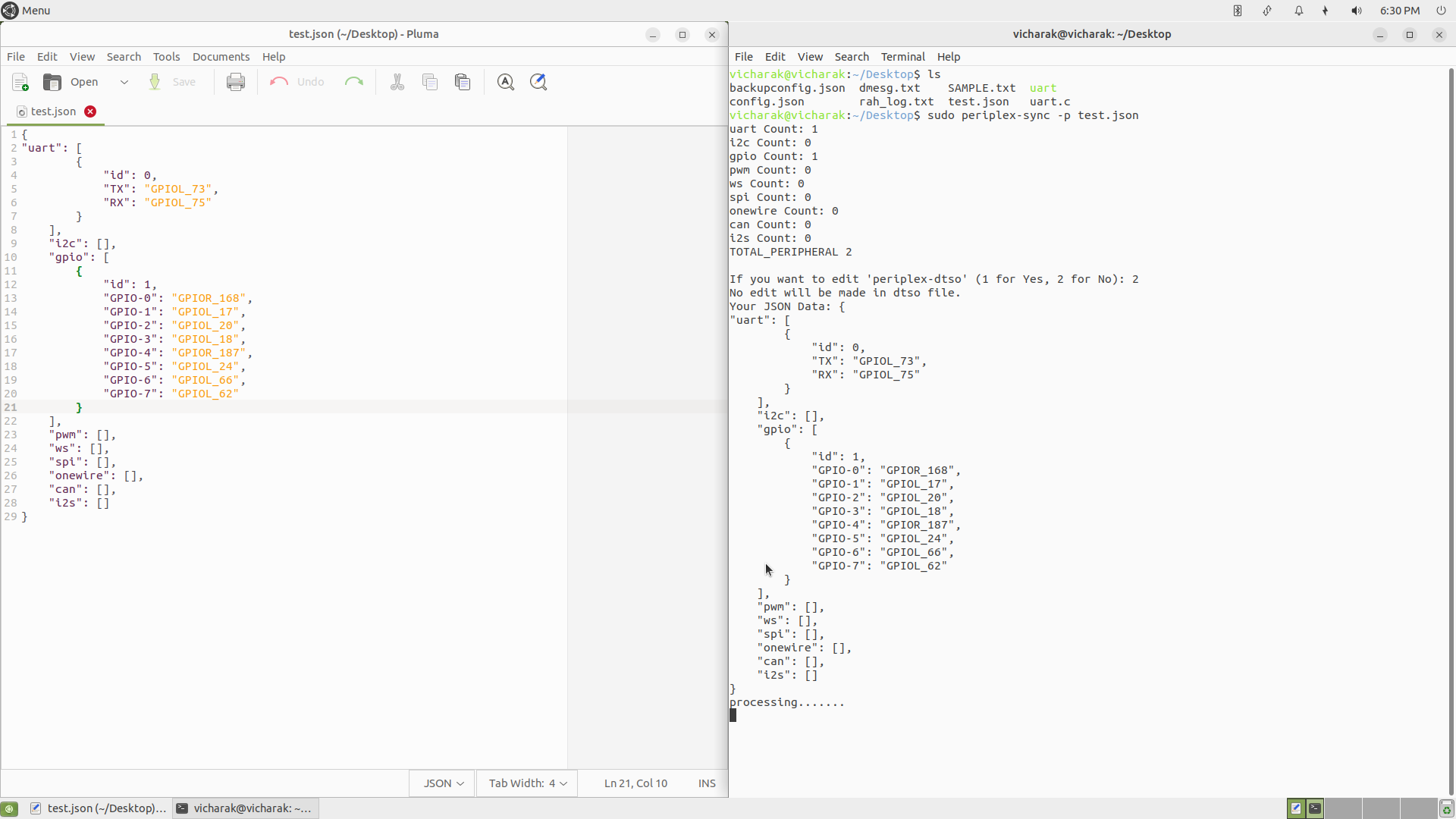
Please try using this JSON file and run the periplex-sync command again.
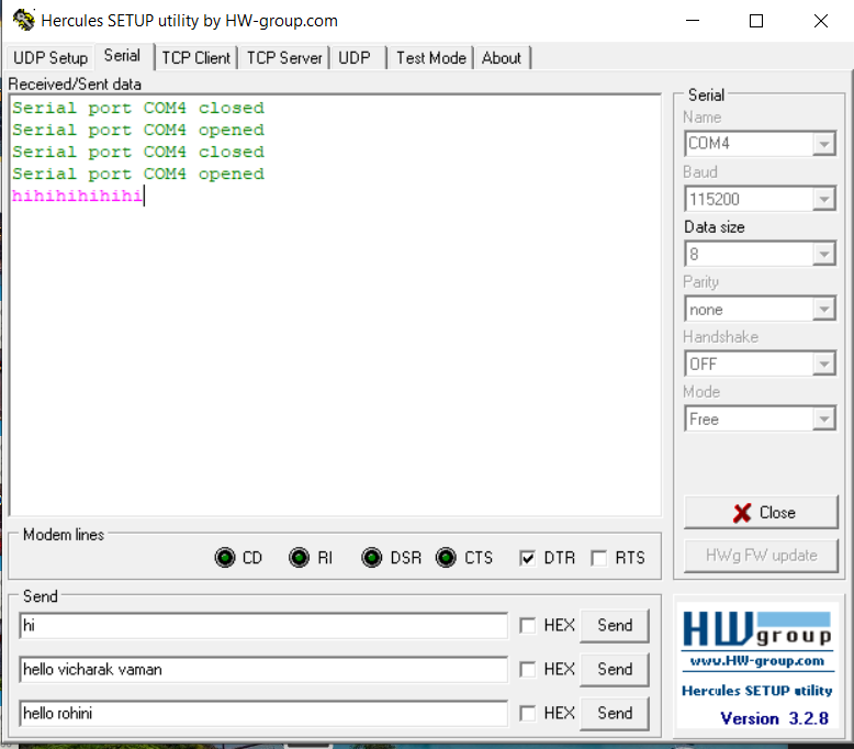
Kindly share a screenshot of the entire process, as I want to verify whether the command executes successfully or not.
Yes, I will try and share the screenshots
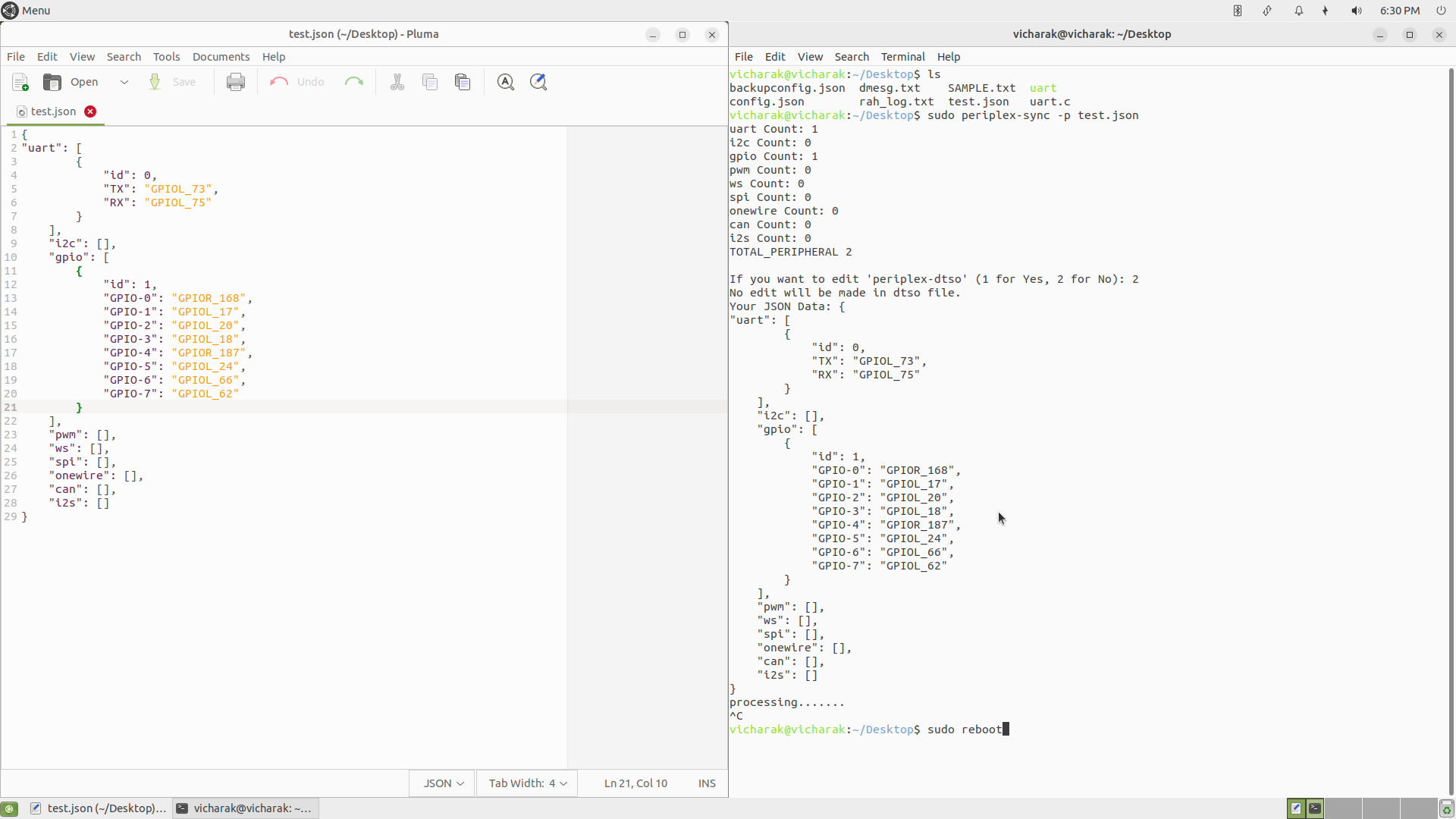
Please do not interrupt the periplex-sync command.
I mean, do not press Ctrl+C while the process is running.
Can anyone please tell me where are these pins physically located on the Vaaman board?
"gpio": [
      {
            "id": 0,
            "GPIO-0": "GPIOT_RXP03",
            "GPIO-1": "GPIOT_RXN03",
            "GPIO-2": "GPIOT_RXP08",
            "GPIO-3": "GPIOT_RXN08",
            "GPIO-4": "GPIOT_RXN21",
            "GPIO-5": "GPIOT_RXP21",
            "GPIO-6": "GPIOT_RXP18",
            "GPIO-7": "GPIOT_RXN18"
      },
      {
            "id": 1,
            "GPIO-0": "GPIOT_RXP06",
            "GPIO-1": "GPIOT_RXN06",
            "GPIO-2": "GPIOT_RXN01",
            "GPIO-3": "GPIOT_RXP01",
            "GPIO-4": "GPIOT_RXP05",
            "GPIO-5": "GPIOT_RXN05",
            "GPIO-6": "GPIOT_RXN20",
            "GPIO-7": "GPIOT_RXP20"
      },
      {
            "id": 2,
            "GPIO-0": "GPIOT_RXP19",
            "GPIO-1": "GPIOT_RXN19",
            "GPIO-2": "GPIOT_RXP02",
            "GPIO-3": "GPIOT_RXN02",
            "GPIO-4": "GPIOT_RXP04",
            "GPIO-5": "GPIOT_RXN04",
            "GPIO-6": "GPIOT_RXP07",
            "GPIO-7": "GPIOT_RXN07"
      },
      {
            "id": 3,
            "GPIO-0": "GPIOT_RXP15",
            "GPIO-1": "GPIOT_RXN15",
            "GPIO-2": "GPIOT_RXP16",
            "GPIO-3": "GPIOT_RXN16",
            "GPIO-4": "GPIOT_RXP09",
            "GPIO-5": "GPIOT_RXN09",
            "GPIO-6": "GPIOT_RXN17",
            "GPIO-7": "GPIOT_RXP17"
      },
      {
            "id": 4,
            "GPIO-0": "GPIOT_RXP12",
            "GPIO-1": "GPIOT_RXN12",
            "GPIO-2": "GPIOT_RXP14",
            "GPIO-3": "GPIOT_RXN14",
            "GPIO-4": "GPIOT_RXP11",
            "GPIO-5": "GPIOT_RXN11",
            "GPIO-6": "GPIOT_RXN13",
            "GPIO-7": "GPIOT_RXP13"
These are LVDS TX/RX pins. To use them, you’ll need the UART Expansion Board Module. If you prefer, you can instead use the standard FPGA pins already available on your Vamman board.
Refer this link for standard FPGA pins available on vaaman:
Refer this link for UART Expansion Board Module:
https://docs.vicharak.in/vicharak_sbcs/vaaman/vaaman-accessories/accessory-uart-expansion-board/
1 Like