It takes more time to process
Please go through this link. I am sending the issue related to the question here, and now I will create a new post
Yes, the timing is dependent on the number of peripherals being generated, Based on your JSON configuration, it will take an average of 10 minutes.
Yes, Done UART Communication
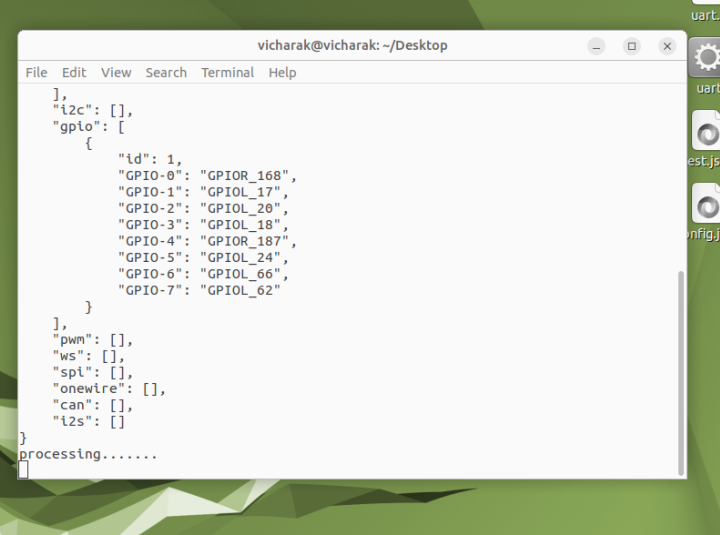
Hello, I want to access the GPIO pins. Can you please tell me the steps?
For detailed instructions on how to generate and interact with GPIOs, please refer to the official documentation at PERIPLEX GPIO | Vicharak
{
“uart”: [
{
“id”: 0,
“TX”: “GPIOL_73”,
“RX”: “GPIOL_75”
}
],
“i2c”: ,
“gpio”: [
{
“id”: 1,
“GPIO-0”: “GPIOR_168”,
“GPIO-1”: “GPIOL_17”,
“GPIO-2”: “GPIOL_20”,
“GPIO-3”: “GPIOL_18”,
“GPIO-4”: “GPIOR_187”,
“GPIO-5”: “GPIOL_24”,
“GPIO-6”: “GPIOL_66”,
“GPIO-7”: “GPIOL_62”
}
],
“pwm”: ,
“ws”: ,
“spi”: ,
“onewire”: ,
“can”: ,
“i2s”:
}
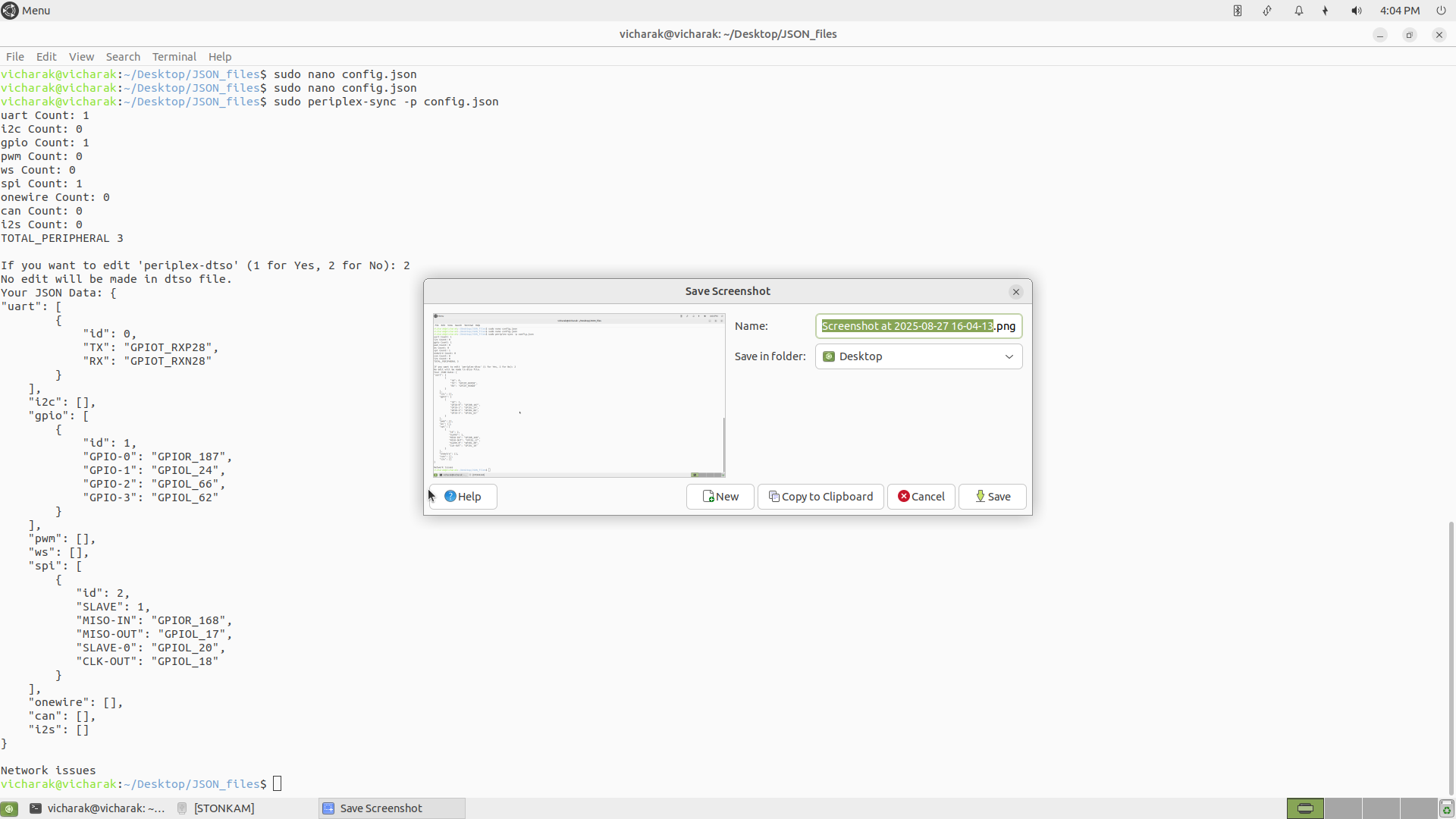
this is the json file
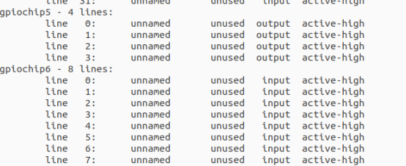
Screenshot after use this sudo gpioinfo
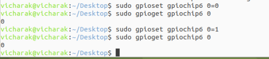
GPIO not set
gpioset & gpioget does not work as you are seeing it, gpioset means you are putting that pin into output mode and setting it’s value HIGH or LOW but when you do gpioget, you are putting that pin into input mode, which means you will detect whatever the voltage is on that GPIO and it will be reflected on the gpioget result e.g. If the pin is getting 3.3V from any source then it will return the output 1 but when there is nothing connected to it and it’s not set to weak pullup it will return 0.
In short, you are sensing the voltage when you are doing gpioget, setting the value to pin does not mean it will hold the voltage when you do gpioget!
You must provide at least 8 pins for the GPIO controller; fewer pins are not allowed. I believe you should no longer face any network issues, as our server processing is now working.
If you are unsure how to create the JSON configuration for the GPIO controller, please refer to the documentation
https://docs.vicharak.in/vicharak_sbcs/vaaman/vaaman-periplex/peripherals/periplex_gpio/
{
“uart”: [
{
“id”: 0,
“TX”: “GPIOT_RXP28”,
“RX”: “GPIOT_RXN28”
}
],
“i2c”: ,
“gpio”: [
{
“id”: 1,
“GPIO-0”: “GPIOR_187”,
“GPIO-1”: “GPIOL_24”,
“GPIO-2”: “GPIOL_66”,
“GPIO-3”: “GPIOL_62”
}
],
“pwm”: ,
“ws”: ,
“spi”: [
{
“id”: 2,
“SLAVE”: 1,
“MISO-IN”: “GPIOR_168”,
“MISO-OUT”: “GPIOL_17”,
“SLAVE-0”: “GPIOL_20”,
“CLK-OUT”: “GPIOL_18”
}
],
“onewire”: ,
“can”: ,
“i2s”:
}
This is the JSON file. I want to configure GPIO as an SPI interface
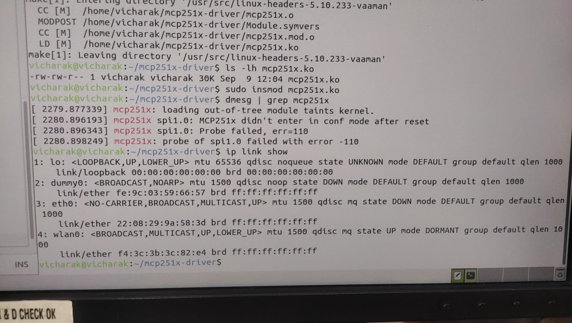
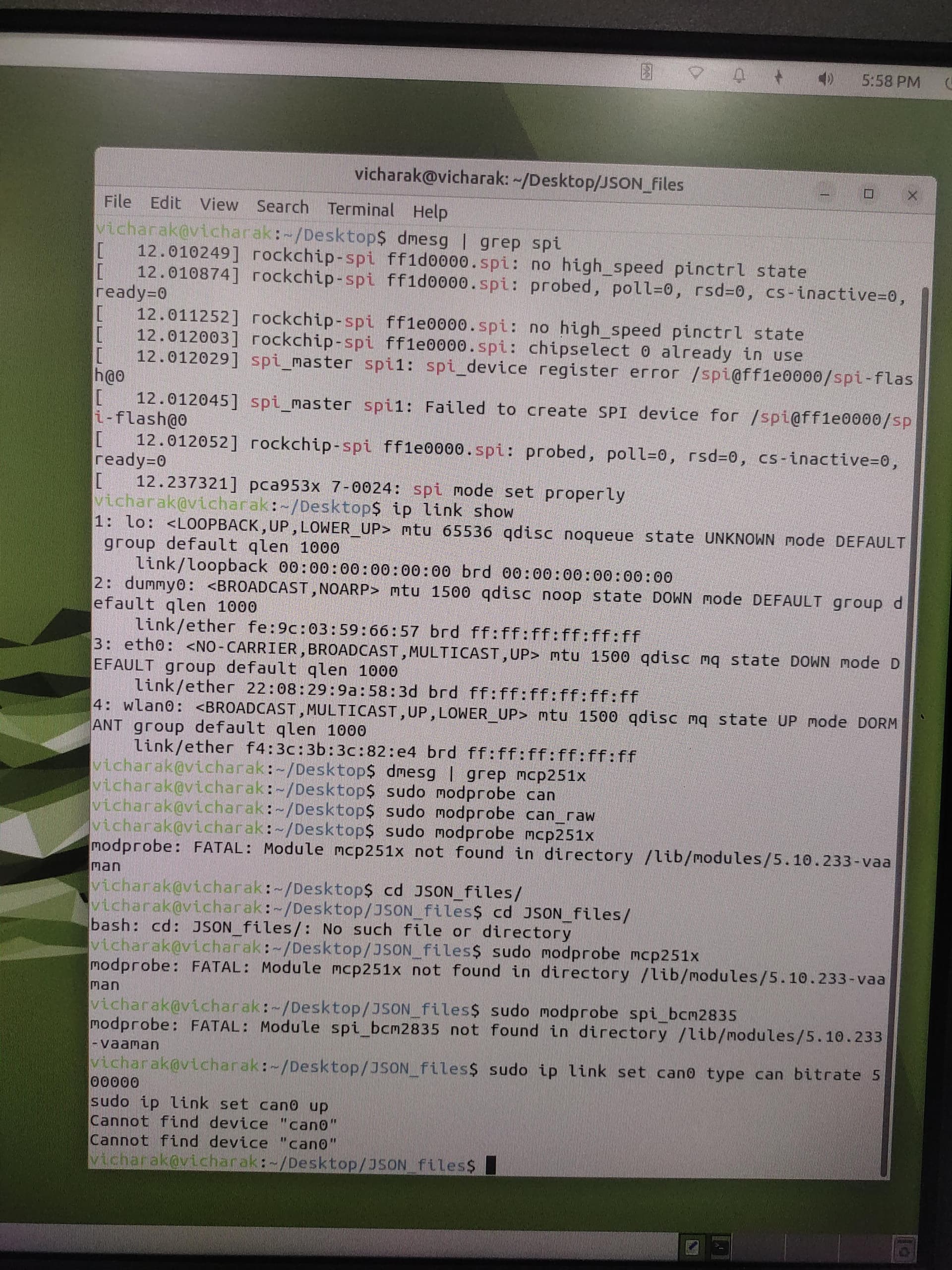
I need SPI pins for the CAN interface.
I am using the MCP2515 CAN module.
Is this the correct file
Please create the correct JSON configuration first; you may refer to the documentation. The correct JSON should be as follows:
{
    "uart": [
        {
            "id": 0,
            "TX": "GPIOT_RXP28",
            "RX": "GPIOT_RXN28"
        }
    ],
    "i2c": [],
    "gpio": [
        {
            "id": 1,
            "GPIO-0": "GPIOR_168",
            "GPIO-1": "GPIOL_17",
            "GPIO-2": "GPIOL_20",
            "GPIO-3": "GPIOL_18",
            "GPIO-4": "GPIOR_187",
            "GPIO-5": "GPIOL_24",
            "GPIO-6": "GPIOL_66",
            "GPIO-7": "GPIOL_62"
        }
    ],
    "pwm": [],
    "ws": [],
    "spi": [
        {
            "id": 2,
            "SLAVE": 1,
            "CLK-OUT": "GPIOR_173",
            "MISO-IN": "GPIOR_174",
            "MOSI-OUT": "GPIOT_RXN27",
            "SLAVE-0": "GPIOT_RXP27"
        }
    ],
    "onewire": [],
    "can": [],
    "i2s": []
}
I personally recommend testing on the processor first before trying it on Periplex. For processor testing, you need to edit the device tree for the SPI node that you want to use, and for the interrupt, you can connect it to one of the processor’s GPIO pins. Editing the SPI node in the device tree for MCP2515 can be a bit tricky, so please proceed carefully.
I am providing the DTSO file for the MCP2512, which uses the processor’s SPI2 interface. Below is the DTSO file:
/dts-v1/;
/plugin/;

#include <dt-bindings/gpio/gpio.h>
#include <dt-bindings/pinctrl/rockchip.h>
#include <dt-bindings/interrupt-controller/irq.h>

&{/} {
    metadata {
        title ="Enable SPI2 MCP2515 (CAN) support on 40 Pin GPIO Header";
        compatible = "vicharak,rk3399-axon", "rockchip,rk3399";
        category = "misc";
        exclusive = "spi2", "GPIO2_B1", "GPIO2_B2", "GPIO2_B3", "GPIO2_B4",
				"GPIO4_D6";
        description = "Enable MCP2515 on SPI2 with 12 MHz Crystal Oscillator.
INT=22";
    };

	can_mcp2515_osc: can-mcp2515-osc {
		status = "okay";
		compatible = "fixed-clock";
		clock-frequency = <12000000>;
		#clock-cells = <0>;
	};
};

&pinctrl {
	mcp2515_int_pin {
		mcp2515_int_pin: mcp2515_int_pin {
			rockchip,pins = <4 RK_PC6 RK_FUNC_GPIO &pcfg_pull_none>;
		};
	};
};

&spi2 {
	status = "okay";
	#address-cells = <1>;
	#size-cells = <0>;

	can_mcp2515: can-mcp2515@0 {
		status = "okay";
		compatible = "microchip,mcp2515";
		reg = <0>;
		interrupt-parent = <&gpio4>;
		interrupts = <RK_PD6 IRQ_TYPE_EDGE_FALLING>;
		spi-max-frequency = <10000000>;
		clocks = <&can_mcp2515_osc>;
		vdd-supply = <&vcc3v3_sys>;
		xceiver-supply = <&vcc3v3_sys>;
		pinctrl-names = "default";
		pinctrl-0 = <&mcp2515_int_pin>;
	};
};
To convert the DTSO file into a DTBO, follow these steps:
-
convert dtso into the dtsi:
cpp -nostdinc -undef -x assembler-with-cpp -E -I /usr/src/linux-headers-$(uname -r)/include -I /usr/lib/modules/$(uname -r)/build/include rk3399-vaaman-spi2-mcp2515.dtso -o rk3399-vaaman-spi2-mcp2515.dtsi -
convert dtsi into the dtbo:
dtc -I dts -O dtb rk3399-vaaman-spi2-mcp2515.dtsi -o rk3399-vaaman-spi2-mcp2515.dtbo -
Copy the generated DTBO file into the overlays directory:
sudo cp rk3399-vaaman-spi2-flash.dtbo /boot/overlays-$(uname -r) -
Update U-Boot to apply the changes:
sudo u-boot-update -
Reboot the board:
sudo reboot
Thank you. I will check and let you know
hello how to interface CAN (MSP2515 module) using SPI pins
I am following all the above steps and also referring to this: https://docs.vicharak.in/vicharak_sbcs/vaaman/vaaman-periplex/peripherals/periplex_spi/