vatsal
September 11, 2025, 4:35am
21
I found the issue: the interrupt pins defined in the overlay DTS were different at both locations. The correct DTS for the overlays is
/dts-v1/;
/plugin/;

#include <dt-bindings/gpio/gpio.h>
#include <dt-bindings/pinctrl/rockchip.h>
#include <dt-bindings/interrupt-controller/irq.h>

&{/} {
    metadata {
        title ="Enable SPI2 MCP2515 (CAN) support on 40 Pin GPIO Header";
        compatible = "vicharak,rk3399-axon", "rockchip,rk3399";
        category = "misc";
        exclusive = "spi2", "GPIO2_B1", "GPIO2_B2", "GPIO2_B3", "GPIO2_B4",
				"GPIO4_D6";
        description = "Enable MCP2515 on SPI2 with 12 MHz Crystal Oscillator.
INT=22";
    };

	can_mcp2515_osc: can-mcp2515-osc {
		status = "okay";
		compatible = "fixed-clock";
		clock-frequency = <12000000>;
		#clock-cells = <0>;
	};
};

&pinctrl {
	mcp2515_int_pin {
		mcp2515_int_pin: mcp2515_int_pin {
			rockchip,pins = <4 RK_PD6 RK_FUNC_GPIO &pcfg_pull_none>;
		};
	};
};

&spi2 {
	status = "okay";
	#address-cells = <1>;
	#size-cells = <0>;

	can_mcp2515: can-mcp2515@0 {
		status = "okay";
		compatible = "microchip,mcp2515";
		reg = <0>;
		interrupt-parent = <&gpio4>;
		interrupts = <RK_PD6 IRQ_TYPE_EDGE_FALLING>;
		spi-max-frequency = <10000000>;
		clocks = <&can_mcp2515_osc>;
		vdd-supply = <&vcc3v3_sys>;
		xceiver-supply = <&vcc3v3_sys>;
		pinctrl-names = "default";
		pinctrl-0 = <&mcp2515_int_pin>;
	};
};
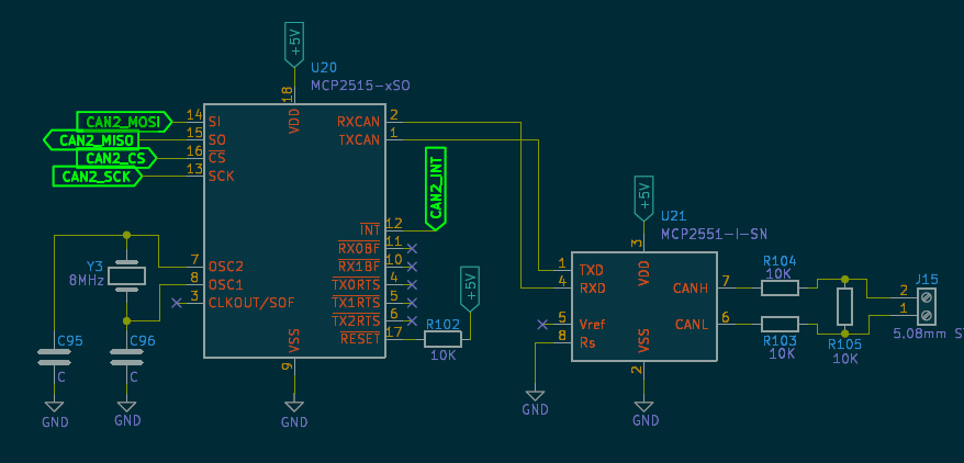
Another important point is that you must connect the pins correctly and provide the proper power supply as mentioned in the IC’s documentation. Any incorrect pin connection will cause errors when probing the MCP251x driver.
If you face any problems, please let me know.
vatsal
September 11, 2025, 4:40am
22
I have connected the MCP2525 IC pins to Vicharak GPIO as follows:
CAN2_MOSI → GPIOT_RXN27
CAN2_MISO → GPIOR_174
CAN2_CS → GPIOT_RXP27
CAN2_SCK → GPIOR_173
Hello @Avi_Shihora @vatsal any updates on this
vatsal
September 12, 2025, 9:48am
25
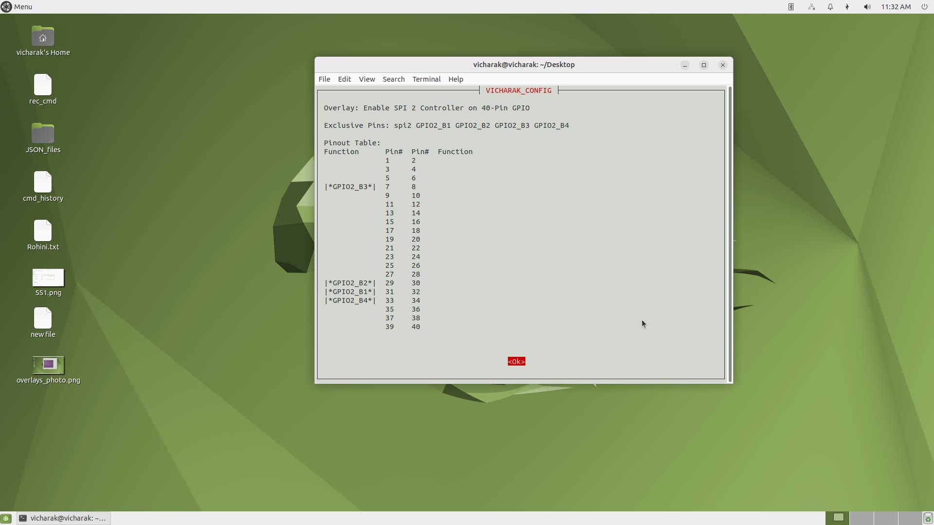
You are testing the MCP2515 IC using the SoC GPIOs Header , so your pin connections should be as follows:
INT → GPIO4_D6 → Pin 37 on SoCSCK → GPIO2_B3 → Pin 7 on SoCMOSI → GPIO2_B2 → Pin 29 on SoCMISO → GPIO2_B1 → Pin 31 on SoCCS → GPIO2_B4 → Pin 33 on SoC
For your reference, all of these pins are already defined in the DTS overlays for SPI2 on the processor.
Please note that the pins GPIOT_RXN27, GPIOR_174, GPIOT_RXP27, and GPIOR_173 are FPGA pins. These are only useful when working with Periplex . They are not used when running applications directly on the SoC (processor).
For Soc pinout guide , Documentation references : Vaaman GPIO Description | Vicharak
For FPGA pinout guide , Documentation references : documentaion:Vaaman GPIO Description | Vicharak
Refer this pdf for more information : https://docs.vicharak.in/_static/files/Vaaman0.3_Pinout_Guide_Rev0.3.pdf
Thank you, I will use the SoC GPIO header pins and check.
I used the following DTSO file:
/dts-v1/;
#include <dt-bindings/gpio/gpio.h>#include <dt-bindings/pinctrl/rockchip.h>#include <dt-bindings/interrupt-controller/irq.h>
&{/} {
can_mcp2515_osc: can-mcp2515-osc {
    status = "okay";
    compatible = "fixed-clock";
    clock-frequency = <12000000>;
    #clock-cells = <0>;
};
};
&pinctrl {
&spi2 {#address-cells = <1>;#size-cells = <0>;
can_mcp2515: can-mcp2515@0 {
    status = "okay";
    compatible = "microchip,mcp2515";
    reg = <0>;
    interrupt-parent = <&gpio4>;
    interrupts = <RK_PD6 IRQ_TYPE_EDGE_FALLING>;
    spi-max-frequency = <10000000>;
    clocks = <&can_mcp2515_osc>;
    vdd-supply = <&vcc3v3_sys>;
    xceiver-supply = <&vcc3v3_sys>;
    pinctrl-names = "default";
    pinctrl-0 = <&mcp2515_int_pin>;
};
};
After that, I ran the following commands:
cpp -nostdinc -undef -x assembler-with-cpp -E
dtc -I dts -O dtb rk3399-vaaman-spi2-mcp2515.dtsi -o rk3399-vaaman-spi2-mcp2515.dtbo
sudo cp rk3399-vaaman-spi2-mcp2515.dtbo /boot/overlays-$(uname -r)/
sudo u-boot-update
sudo reboot
After rebooting, I checked with the following commands, but can0 was not showing up:
dmesg | grep mcp2515
ls /dev/spidev*
ip link | grep can
vatsal
September 15, 2025, 5:12am
28
What is the dmesg log when you insert the mcp251x.ko module? Please provide it as a file named dmesg.txt by running the following command:
sudo dmesg > dmesg.txt
Please check the dmesg file
vatsal
September 15, 2025, 9:23am
31
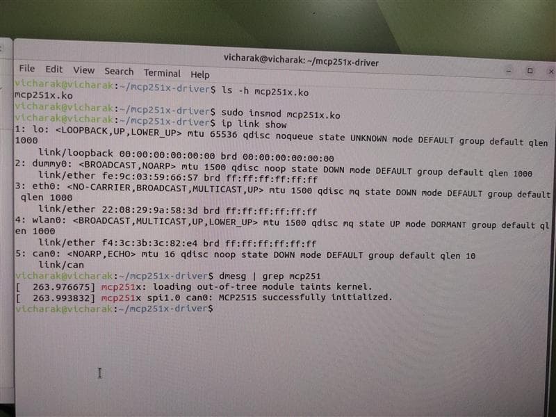
First, insert the mcp251x.ko module the same way you did before. After that, I will check the dmesg log to identify the error you faced during insmod. You have done this step in the past, so please insert the module manually and then send me the dmesg log, because right now I don’t see any messages related to mcp251x in your dmesg
Okay I will check it again and let you know
demesg1.txt (45.5 KB)
vicharak@vicharak:~/mcp251x-driver$ ls
vatsal
September 16, 2025, 5:55am
34
I can see that your probe has failed. This could be due to an issue with the connections, the overlays, or even the hardware itself.
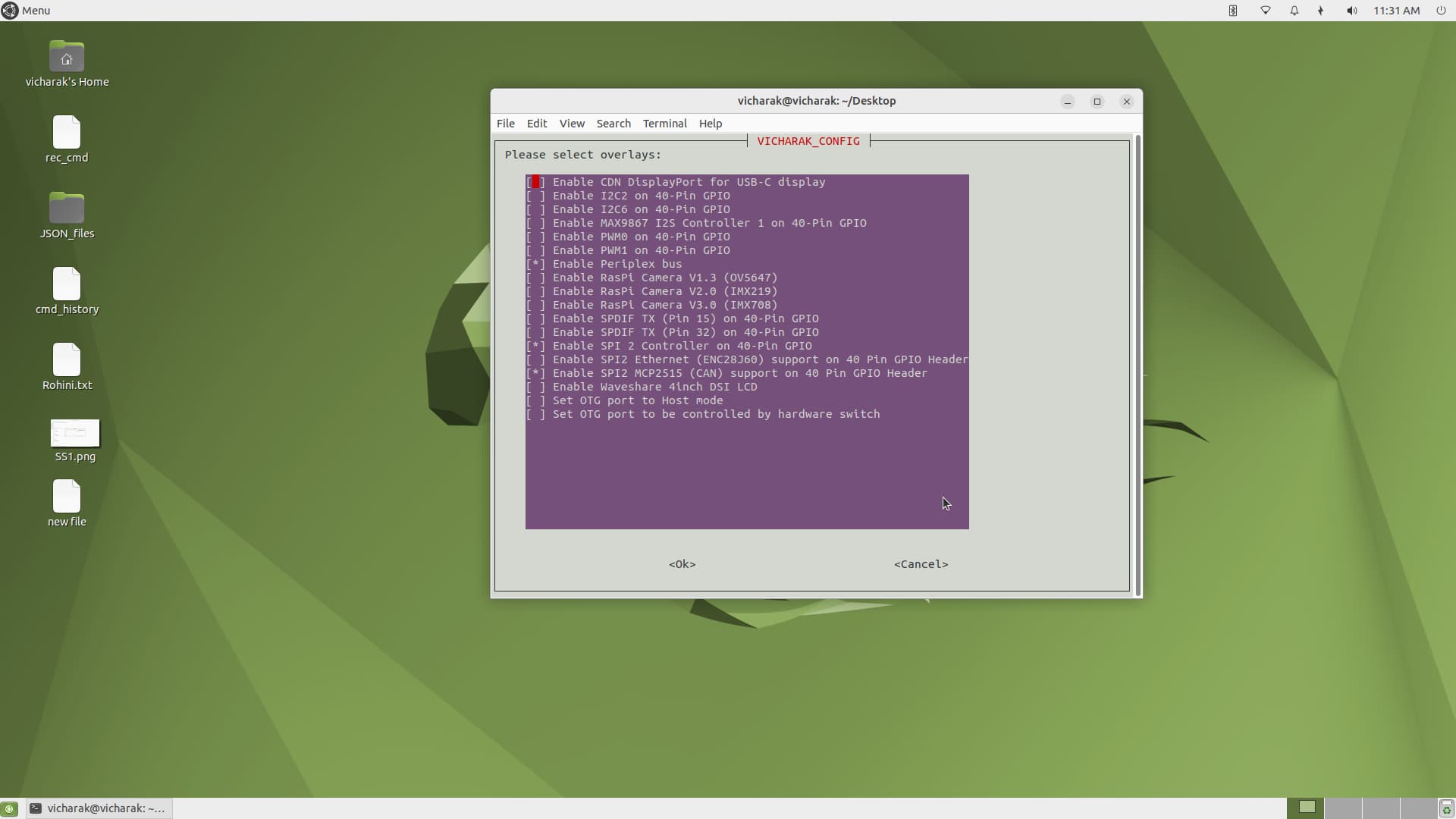
Please provide me with a screenshot of Manage Overlays from vicharak-config.
Steps:
Run sudo vicharak-config
Select Overlays
Open Manage Overlays
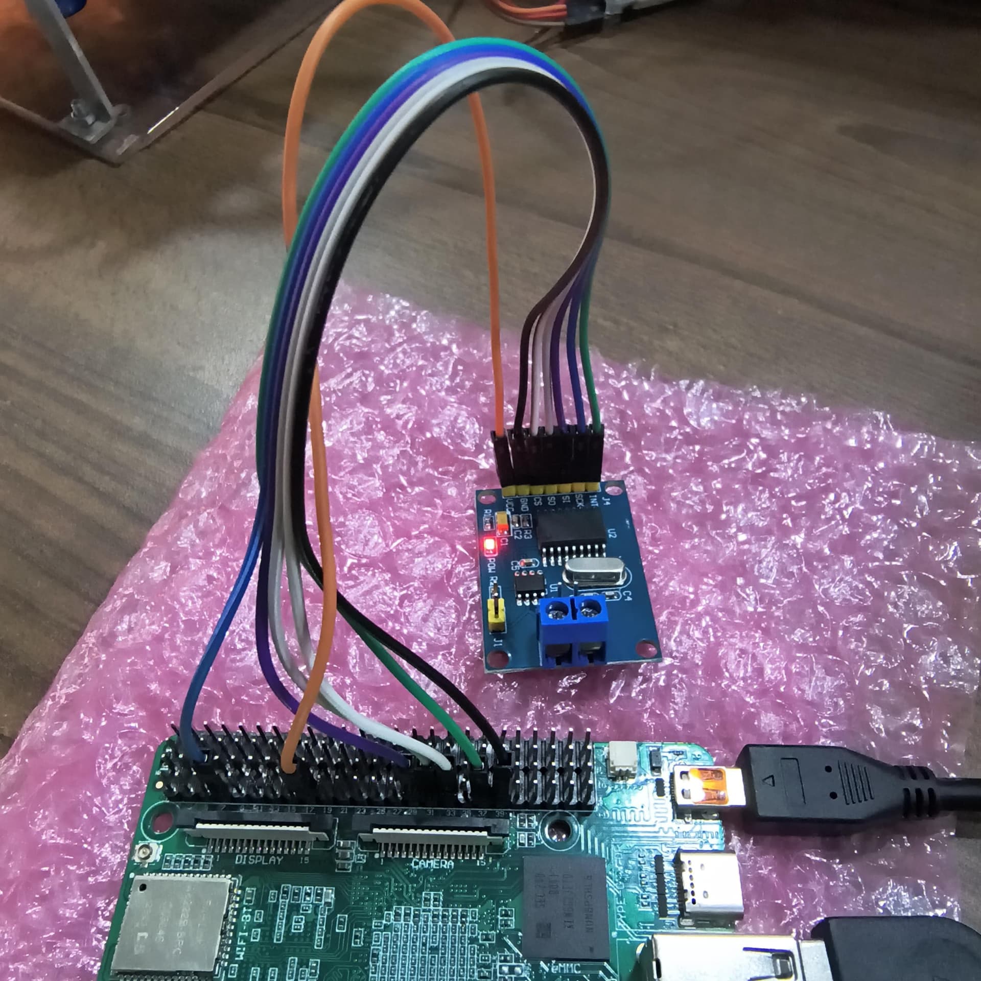
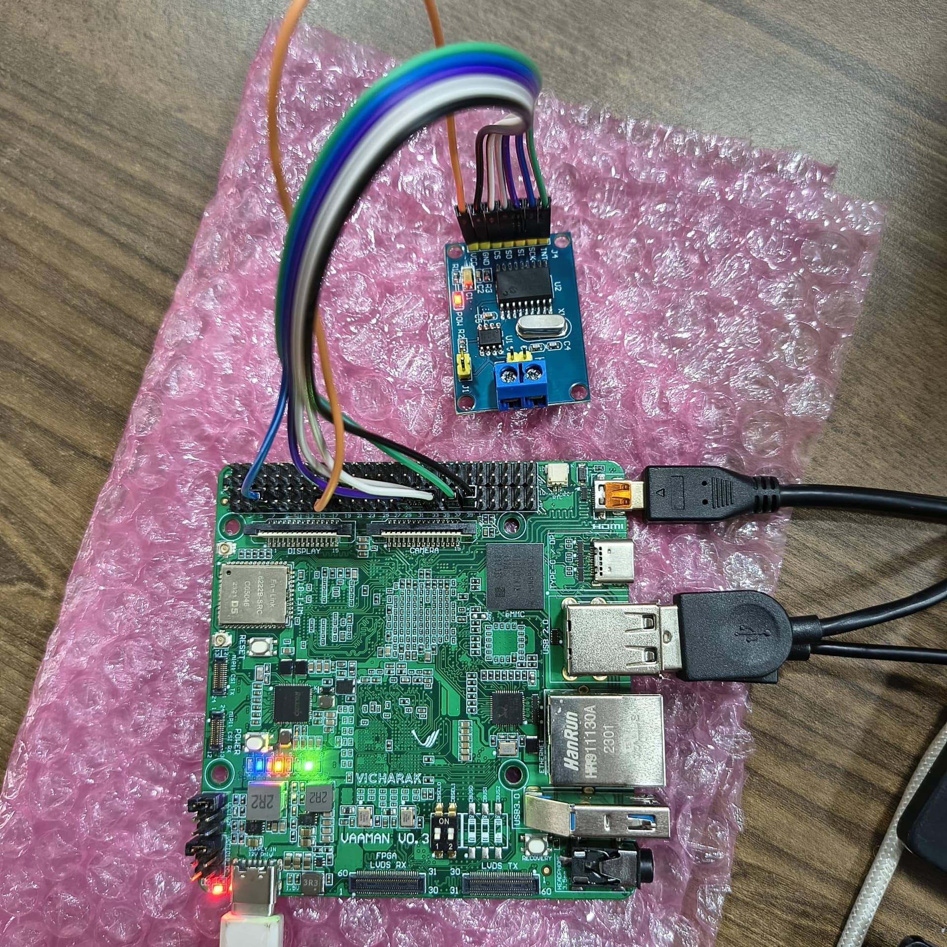
Additionally, I need a photo of how you have connected the MCP2515 CAN module to the Vaaman board, so I can verify your hardware connections.
vatsal
September 16, 2025, 10:50am
38
Turn off the “Enable SPI 2 Controller on 40-pin GPIO” overlay because the &spi2 node cannot be used twice in the device tree. Make sure not to disable the “Enable SPI 2 MCP2515 (CAN) support on 40-pin GPIO header” overlay. After these changes, it should work.
Now it is showing can0. I am connecting the MCP2515 module with 3.3V.
can_receive.zip (803 Bytes)
I am running this code to receive data from the USB-CAN-TOOL, but I am not receiving any data.
vatsal
September 22, 2025, 12:05pm
41
To use cansend, candump, and other CAN utilities, you need to install the can-utils package. These tools provide user-space utilities for interacting with CAN interfaces via the Linux SocketCAN subsystem.
sudo apt install can-utils
Identify CAN Interfaces:
Bring Up a CAN Interface:
To bring up a CAN interface, use the following command:
sudo ip link set <interface> type can bitrate <bitrate_value>
Example:
to bring up can0 with a bitrate of 500 kbps, you would run:
sudo ip link set can0 up type can bitrate 500000
can0 is the name of the CAN interface,500000 is the bitrate in bits per second.
Sending CAN Frames:
To send a CAN frame, use the cansend command:
sudo cansend <interface> <arbitration_id>#<data_bytes>
<interface>: The CAN interface name (like can0).
<arbitration_id>: The CAN identifier (11-bit or 29-bit).
Standard Frame: 11-bit ID (range: 0x000 – 0x7FF).
Extended Frame: 29-bit ID (range: 0x00000000 – 0x1FFFFFFF).
<data_bytes>: Up to 8 data bytes in hexadecimal format, concatenated without spaces.
Example:
Send a standard frame with ID 0x7E8 and 7 bytes of data:
sudo cansend can0 7E8#11223344556677
Send an extended frame with ID 0x18DAF110 and 8 bytes of data:
sudo cansend can0 18DAF110#1122334455667788
Receiving CAN Frames: \
To receive CAN frames, use the candump command
sudo candump <interface>
Example:
sudo candump can0
To filter by a specific ID, use:
sudo candump can0,7E8:7FF
7E8:7FF means show only messages with ID 0x7E8