In this tutorial, the CAN network is established between two Arduinos. You can achieve the same setup between the Vaaman board and an Arduino, or between the Vaaman board and an ESP.
Refer to this video: https://www.youtube.com/watch?v=spVgKZkNpT8 , it explains how communication occurs between two MCP2515 modules, where the CAN network is established between two ESP32 boards. In our case, we have the Vaaman board on one side, and you can connect any compatible device on the other side to establish communication.
You can refer to this code for the ESP, as I have tested it and it works correctly,
// Simple sketch that querries OBD2 over CAN for coolant temperature
// Showcasing simple use of ESP32-TWAI-CAN library driver.

// Default for ESP32
#define CAN_TX        21
#define CAN_RX        20

CanFrame rxFrame;

void sendObdFrame(uint8_t obdId) {
    CanFrame obdFrame = { 0 };
    obdFrame.identifier = 0x7DF; // Default OBD2 address;
    obdFrame.extd = 0;
    obdFrame.data_length_code = 8;
    obdFrame.data[0] = 2;
    obdFrame.data[1] = 1;
    obdFrame.data[2] = obdId;
    obdFrame.data[3] = 0xAA;    // Best to use 0xAA (0b10101010) instead of 0
    obdFrame.data[4] = 0xAA;    // CAN works better this way as it needs
    obdFrame.data[5] = 0xAA;    // to avoid bit-stuffing
    obdFrame.data[6] = 0xAA;
    obdFrame.data[7] = 0xAA;
    // Accepts both pointers and references
    ESP32Can.writeFrame(obdFrame);  // timeout defaults to 1 ms

    Serial.println("Sending frame");
}

void setup() {
    // Setup serial for debbuging.
    Serial.begin(115200);

    // Set pins
    ESP32Can.setPins(CAN_TX, CAN_RX);

    // You can set custom size for the queues - those are default
    ESP32Can.setRxQueueSize(5);
    ESP32Can.setTxQueueSize(5);

    // .setSpeed() and .begin() functions require to use TwaiSpeed enum,
    // but you can easily convert it from numerical value using .convertSpeed()
    ESP32Can.setSpeed(ESP32Can.convertSpeed(500));

    // You can also just use .begin()..
    if(ESP32Can.begin()) {
        Serial.println("CAN bus started!");
    } else {
        Serial.println("CAN bus failed!");
    }

    // or override everything in one command;
    // It is also safe to use .begin() without .end() as it calls it internally
    if(ESP32Can.begin(ESP32Can.convertSpeed(500), CAN_TX, CAN_RX, 10, 10)) {
        Serial.println("CAN bus started!");
    } else {
        Serial.println("CAN bus failed!");
    }
}

void loop() {
    static uint32_t lastStamp = 0;
    uint32_t currentStamp = millis();

    if(currentStamp - lastStamp > 1000) {   // sends OBD2 request every second
        lastStamp = currentStamp;
        sendObdFrame(5); // For coolant temperature
    }

    // You can set custom timeout, default is 1000
    if(ESP32Can.readFrame(rxFrame, 1000)) {
        // Comment out if too many frames
        Serial.printf("Received frame: %03X  \r\n", rxFrame.identifier);
        if(rxFrame.identifier == 0x7E8) {   // Standard OBD2 frame responce ID
            Serial.printf("Collant temp: %3d°C \r\n", rxFrame.data[3] - 40); // Convert to °C
        }
    }
}
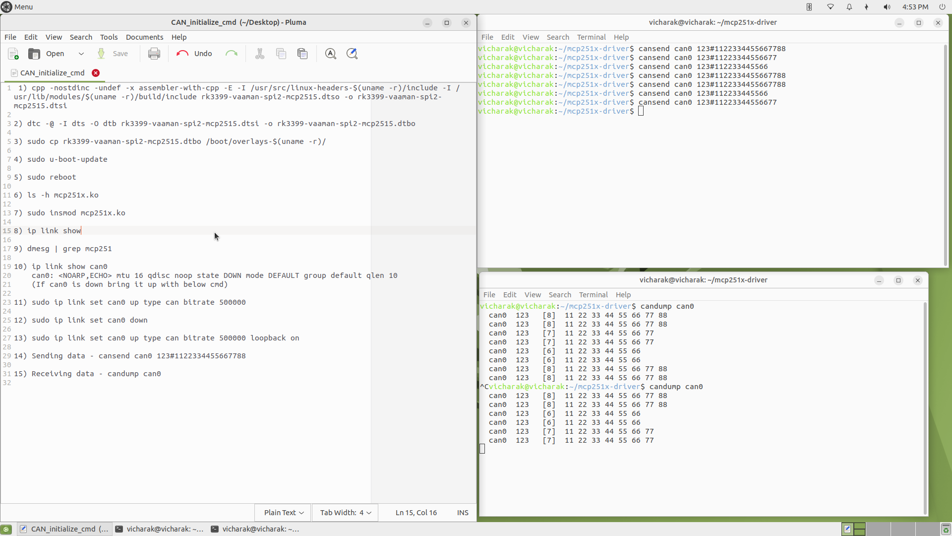
Once the setup is properly completed, you can send the following command from the Vaaman board cansend can0 7E8#0341058700000000
To receive data from the ESP, run the following command on the Vaaman board to monitor incoming messages: candump can0
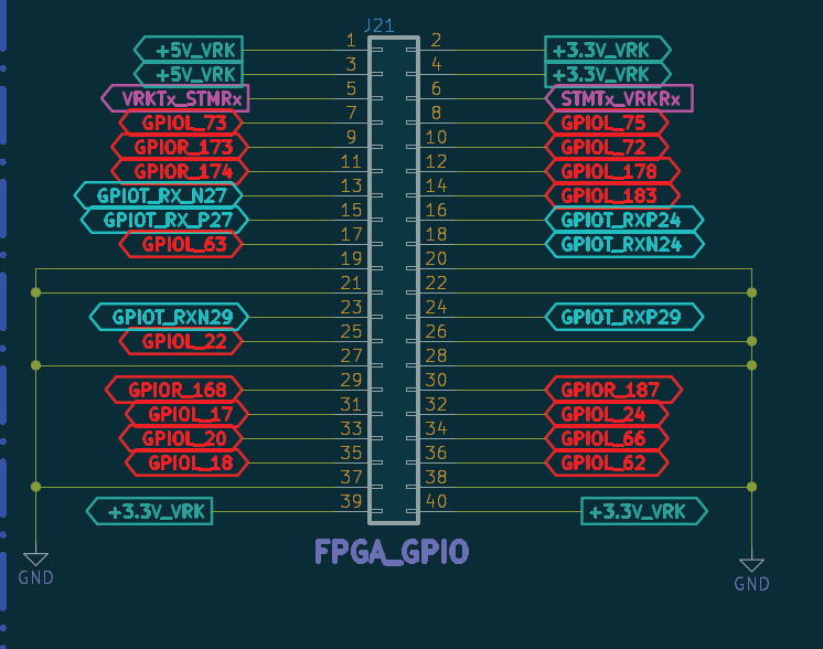
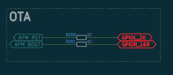
I am using FPGA GPIO pins for firmware flashing on an STM32F105.
Pin 29 → GPIOR_168
Pin 33 → GPIOL_20
These GPIOs are connected to the STM32 and are used during the firmware flashing process.
However, I am facing an issue where the GPIOs are not getting handled properly.
Even though I am running the code and flashing the firmware from the Vicharak board to the STM32, the GPIO pins are not responding / not toggling, due to which the required functionality is not working.
Please help to identify why the GPIO handling is not working and how to debug or fix this issue.
You can use either balenaEtcher or dd.
BalenaEtcher - Open and select the image and select the SDCard device and click on flash.
For dd you can do this way,
Please let me know when it is fixed.
Also, tell me which gpiochip these two pins belong to (gpiochip1 or gpiochip2): Pin 29 → GPIOR_168, Pin 33 → GPIOL_20